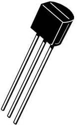
J112
JFET AMMORA FET-RFSS. JFET N-Channel Switch. JFET N-Channel Transistor General Purpose. P-channel JFET, ON Semiconductor. The J113 from Fairchild is a through hole, N channel switch in TO-92 package. This device is designed for low level analogue switching, sample and hold circuits and chopper stabilized amplifiers. Source and drain are interchangeable Gate to source breakdown voltage of 35V.
Fairchild Semiconductor | Купить | ||||||||||||||||||||||||||||||||||||||
| IC SWITCH N-CHAN 35V 50MA TO-92 | |||||||||||||||||||||||||||||||||||||||
Категория: | Discrete Semiconductor Products | ||||||||||||||||||||||||||||||||||||||
| -- | |||||||||||||||||||||||||||||||||||||||
Год: | 06+ | ||||||||||||||||||||||||||||||||||||||
Datasheet (Техническое описание) J112 Поиск в бесплатном архиве даташитов datasheet.su Посмотреть все характеристики
| |||||||||||||||||||||||||||||||||||||||
J113 Jfet Datasheet
 Transconductance
The ability of a JFET to amplify is described as trans-conductance and is merely the change in drain current divided by the change in gate voltage. It is indicated as Mhos or Siemens and is typically 2.5mmhos to 7.5mmhos for the MPF102 transistor. Because of the high input impedance, the gate is considered an open circuit and draws no power from the source. Although voltage gain appears low in a JFET, power gain is almost infinite.
Drain Characteristics
Even though no voltage appears at the gate, a substantial amount of current will flow from the drain to the source. In fact, the JFET does not actually turn off until the gate goes several volts negative. This zero gate voltage current through the drain to the source is how the bias is set in the JFET. Resistor R3, which is listed in the above diagram, merely sets the input impedance and insures zero volts appears across the gate with no signal. Resistor R3 does almost nothing for the actual biasing voltages of the circuit. When the gate voltage goes positive, drain current will increase until the minimum drain to source resistance is obtained and is indicated below:
Minimum Rds(on) or On State Resistance
The above value can be determined by reading specification sheets for the selected transistor. In cases where it is not known, it is safe to assume it is zero. The other important characteristic is the absolute maximum drain current. Listed below are absolute maximum drain currents for some common N-channel transistors:

Transistor Jfet J113
- MPF102 - 20ma
- 2N3819 - 22ma
- 2N4416 - 15ma

When designing a JFET circuit, it is highly recommended to prevent the absolute maximum current from being exceeded under any conditions. In design calculations. never use more than 75% of the maximum drain current as specified by the manufacturer.
JFET Design Example 1
For the first design example, we will use an MPF102 transistor with a Vcc of 12 volts. We will allow no more than 5 ma of drain current under any circumstances. For resistor R3, the gate resistor, we will use 1 Meg for a very high impedance across the gate. The gate resistor is normally anywhere from 1 Meg to 100K. The higher values allow the JFET to amplify very weak signals but require measures to prevent oscillations. The lower values enhance stability but tend to decrease gain. Sometimes the value of this resistor needs to be adjusted for impedance matching depending on the type of signal source involved. Because we will only allow 5 ma of current through the drain to source, we will calculate the total resistance for resistors R1 and R2. We will assume the Minimum Rds(on) to be zero.
Vcc = 12
Minimum Rds(on) = 0
Ids = 5 ma
(Vcc - (Minimum Rds(on) * Ids)) / Ids = Total Resistance of R1 and R2
(12 - (0 * .005) ) / .005 = 2400 ohms
To calculate R2, we must select the desired voltage drop across this resistor. it is normally set between 20 to 30% of Vcc. For this example we will set R2 to 25% of the supply voltage (minus any voltage dropped across the drain and source) as follows:
R2 = .25 * Total Resistance of R1 and R2
R2 = .25 * 2400 = 600 ohms (nearest standard value is 560 ohms)
R2 = 560 ohms
R1 can now be easily calculated by subtracting R2 from the total resistance as follows:
